Cargo racks are too expensive for what they are (tubes welded together) and they also don't come in small sizes fit for the top of a standard truck cab. As part of preparing my truck for the ford flophouse build I wanted a place to store dirty or smelly cargo like a gas can, oil, or dirty muddy boots that wouldn't mess up the inside of the camper. The idea would be to build a small roof basket, attach one a bright LED light bar for improved night visibility, and bolt it to the top of my truck.
Designing
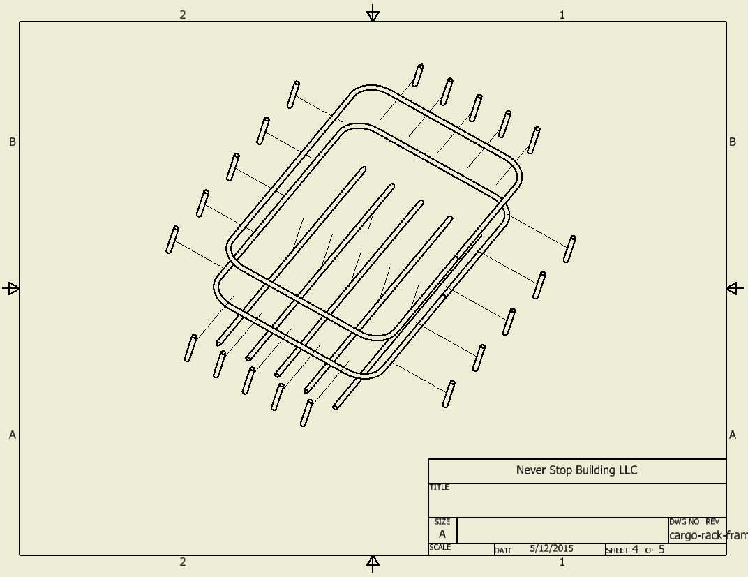
I mocked up the basic frame in Inventor, not shown are the made to fit brackets for the mount points and light bar. You'd want to fab these up per your individual needs. Also not shown in the model is that the bottom of the basket will be covered with a sheet of expanded steel sheet.

Basic Concept

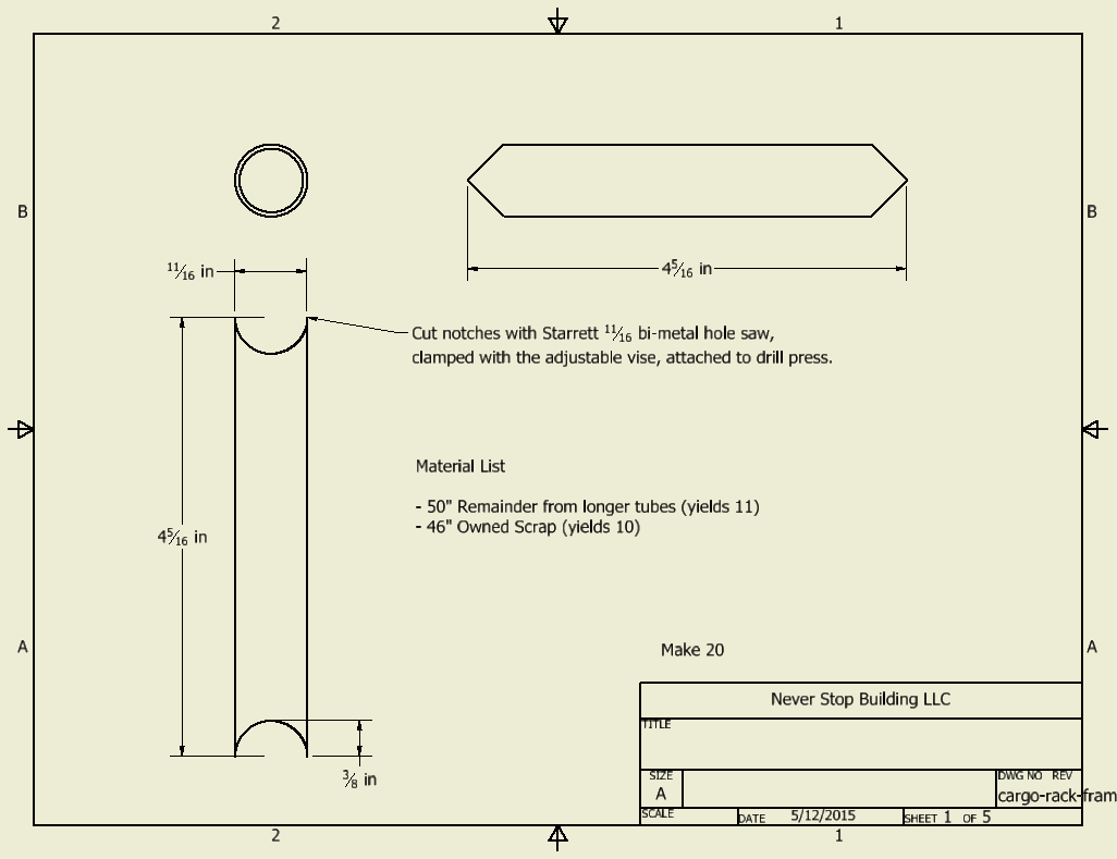
Small Tube

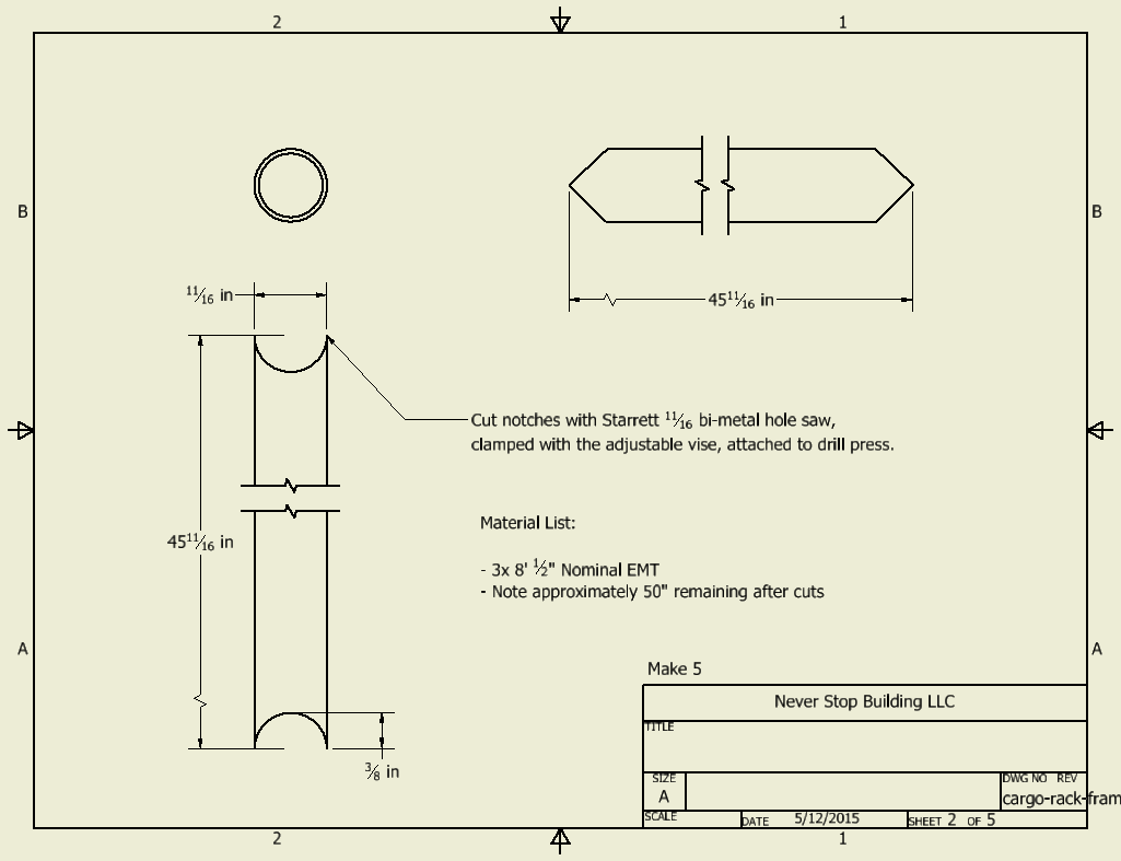
Large Tube

Upper and Lower Hoops

Assembly Instructions
Sourcing Materials
I wanted to keep this project inexpensive so it will be constructed out of 1/2" EMT conduit. While I'll have to be careful to prep the surfaces because welding galvanized coating is VERY dangerous, it's hard to beat the price of about $2.50 for a 10 foot section at Home Depot. Here is a rough material list:
- 6x 10' 1/2" EMT conduit ($2.50 each) I also had some at home.
- 1/8" scrap steel plate for brackets
- 27.5" x 45.5" Expanded sheet 16 Gauge, 1/2" x 3/4" openings ($25.82)
- 4x Neoprene Vibration Damping Sandwich Mount, Male/Male, 5/16"-18 Thread, 1-1/4" High, 1-1/4" Wide to mount to truck roof ($2.45 each)
- Paint and Primer (~$7)
You'll also need associated nuts, washers, and material to weld, etc. I'm using nylock nuts to bolt the thing to the roof, and will add a little silicon just to be safe. I didn't include the light bar in the materials as it's both optional and expensive. Mine was about $90 on Amazon though the price may have changed since I purchased it.
So all in, assuming you have a good set of tools at your disposal, material cost is around $60 for the basket.
Construction
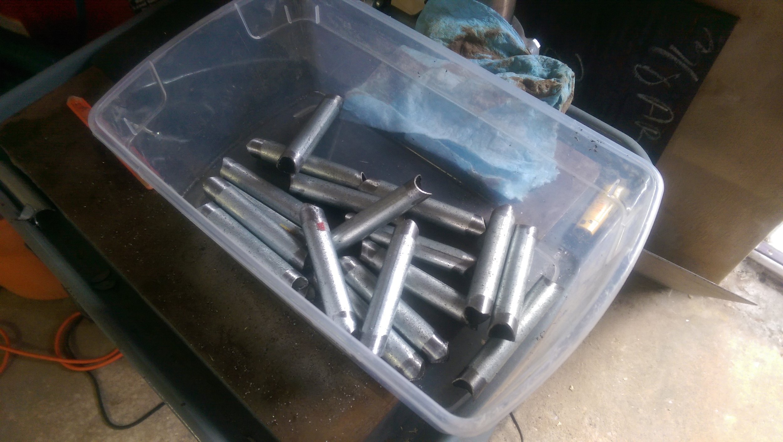
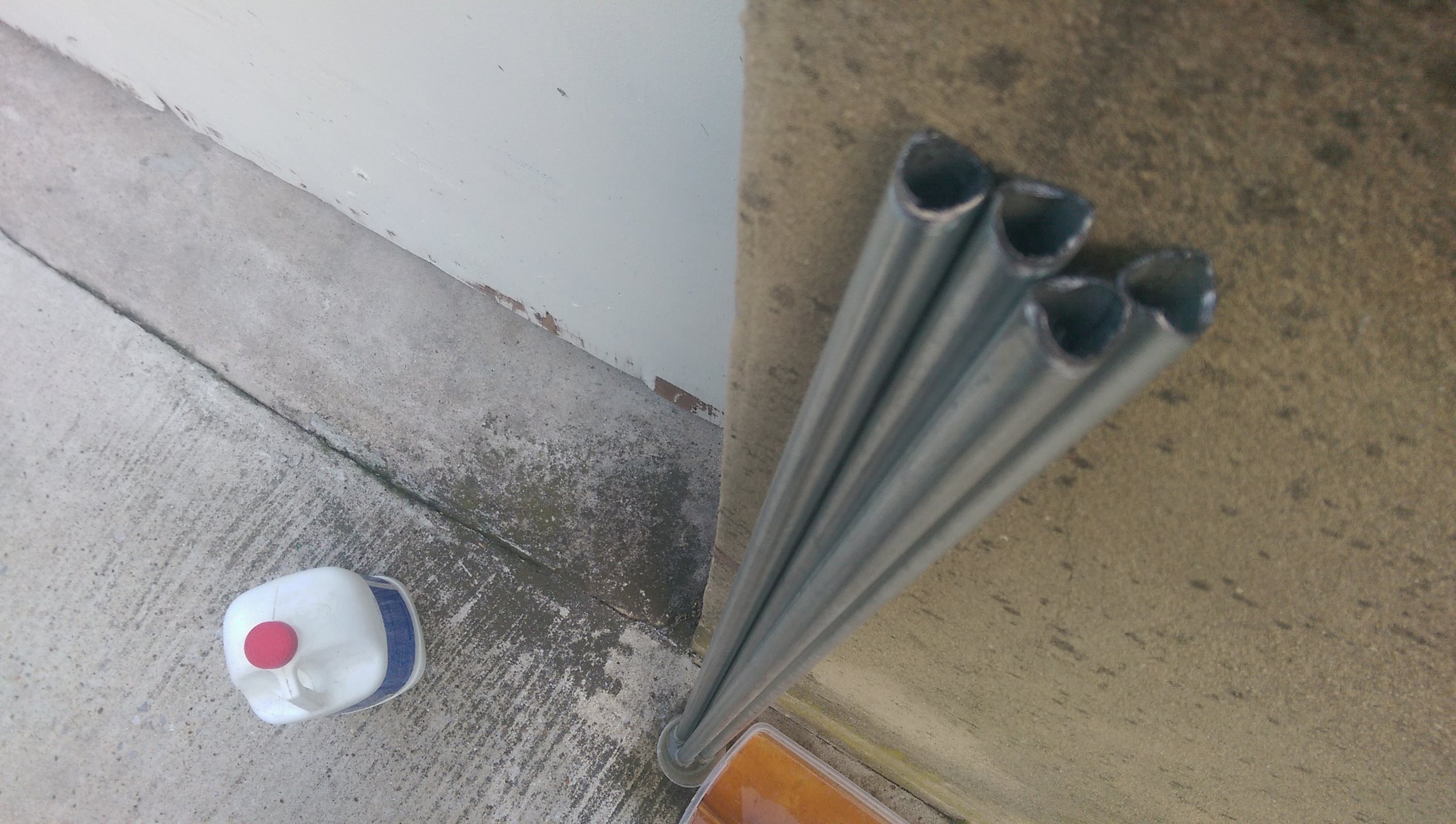
I started by cutting the small tubes to length with a pipe cutter:

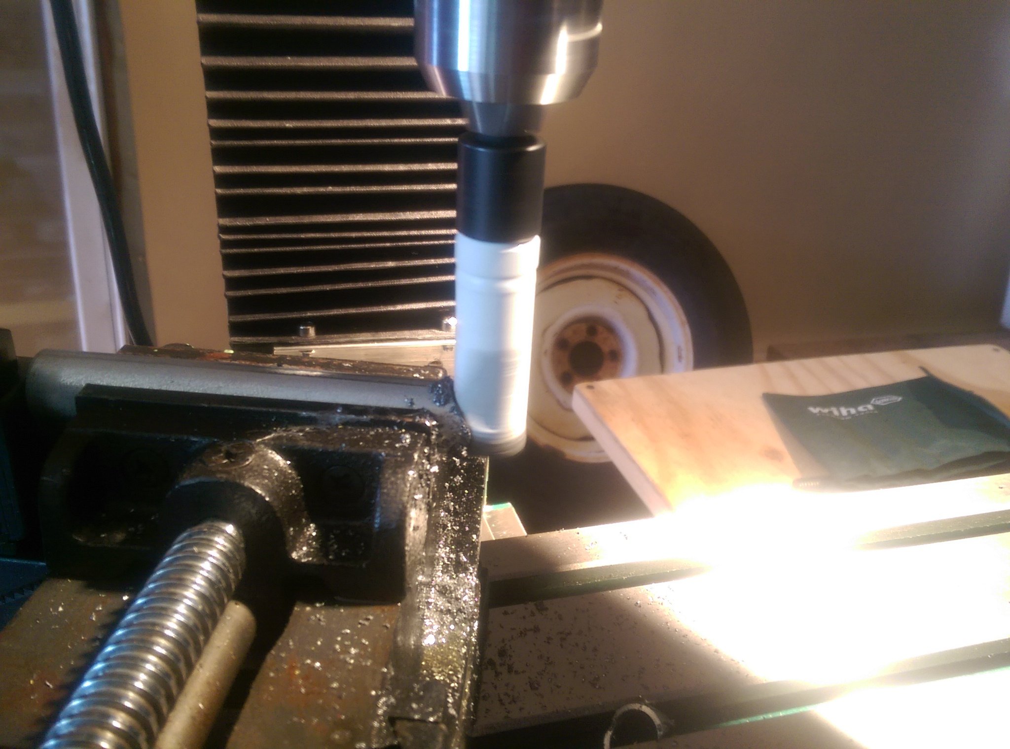
Then used a 3/4" hole saw in my milling machine to notch each end. This was a painful and annoying process. I blew through 2 hole saws trying to get the thing dialed in on a drill press, but in the end, I should have used the mill. I ran about 500 rpm and used plenty of oil:
There are 5 upright tubes to each side, 20 tubes, 40 cuts, 40 cleaning operations... Fun!

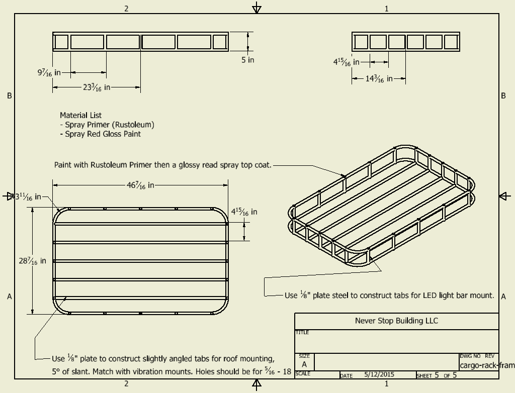
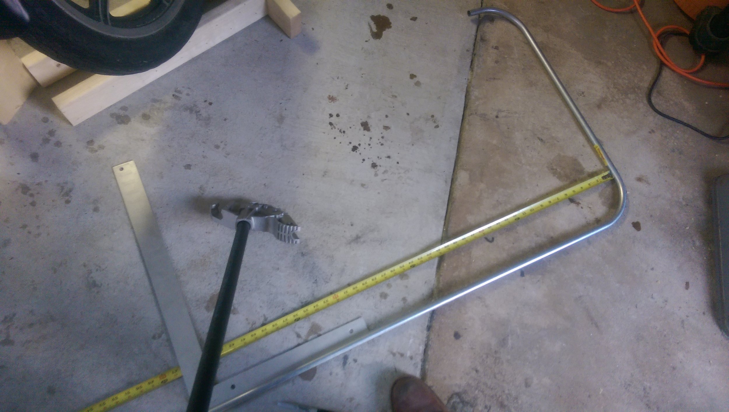
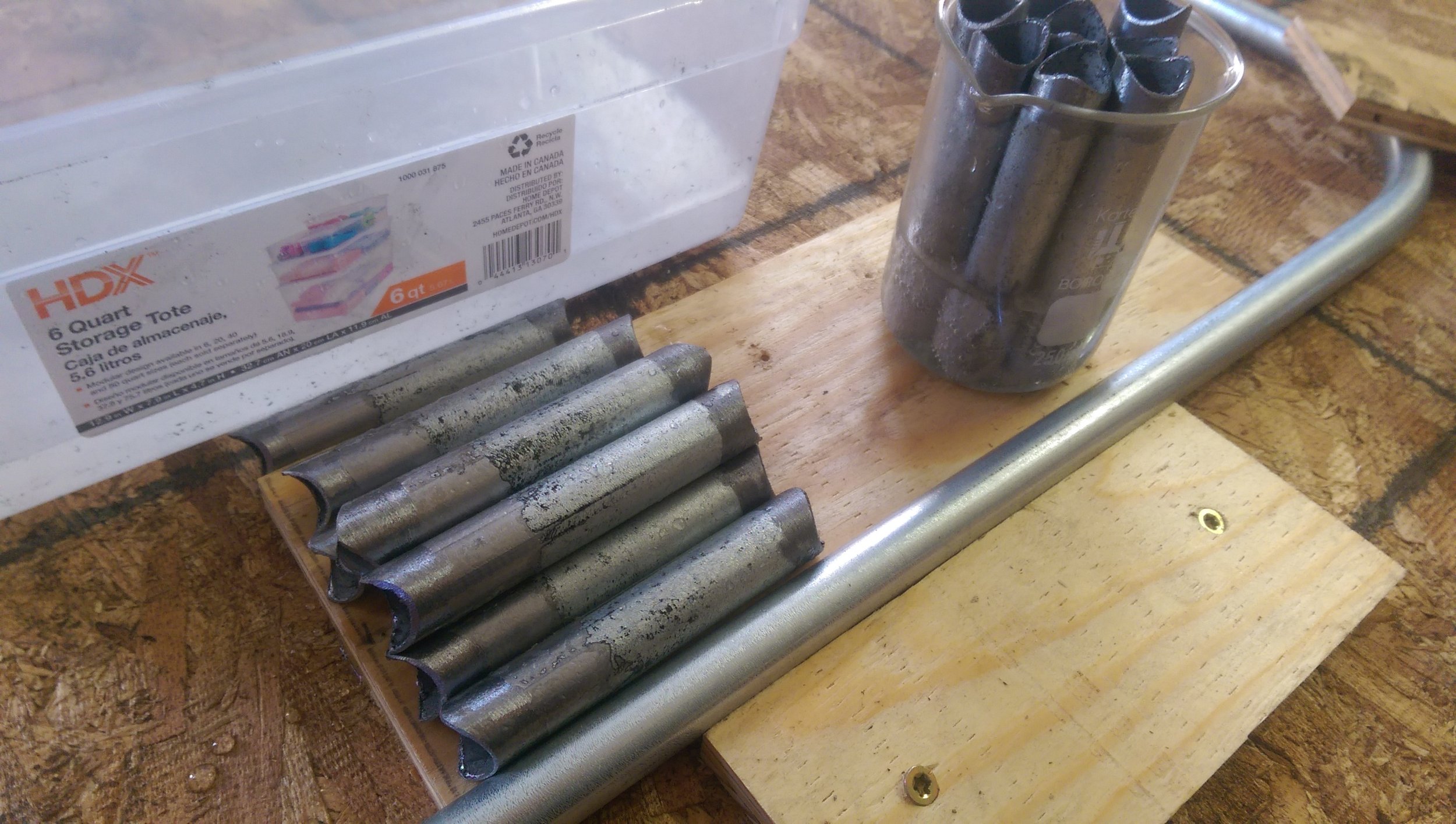
I used a conduit bender to bend the upper and lower hoops. It was seemingly hard to find a quick answer to how to use the bender. So how do you layout a conduit bend? Measure the distance from some "end" to where you want the back of the 90 degree bend to be. In my case I had an outside measurement of 46 7/16" so I measured from the outside of one corner bend to the unbent portion and marked there. Then I lined up that mark with the Star mark on the bender and bent it:

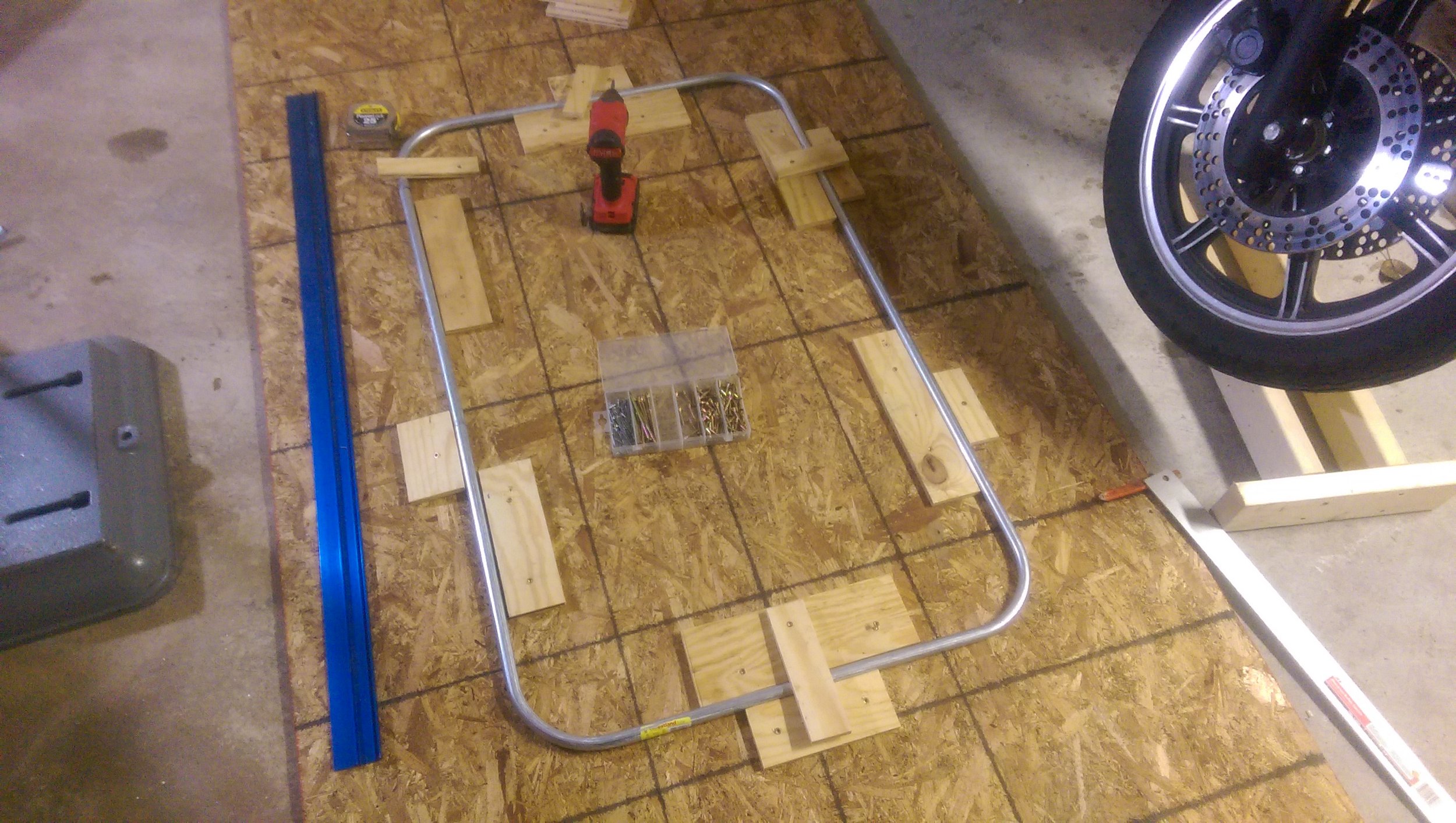
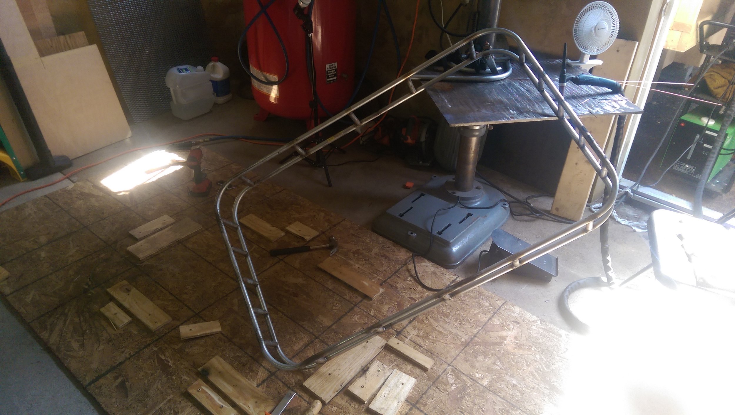
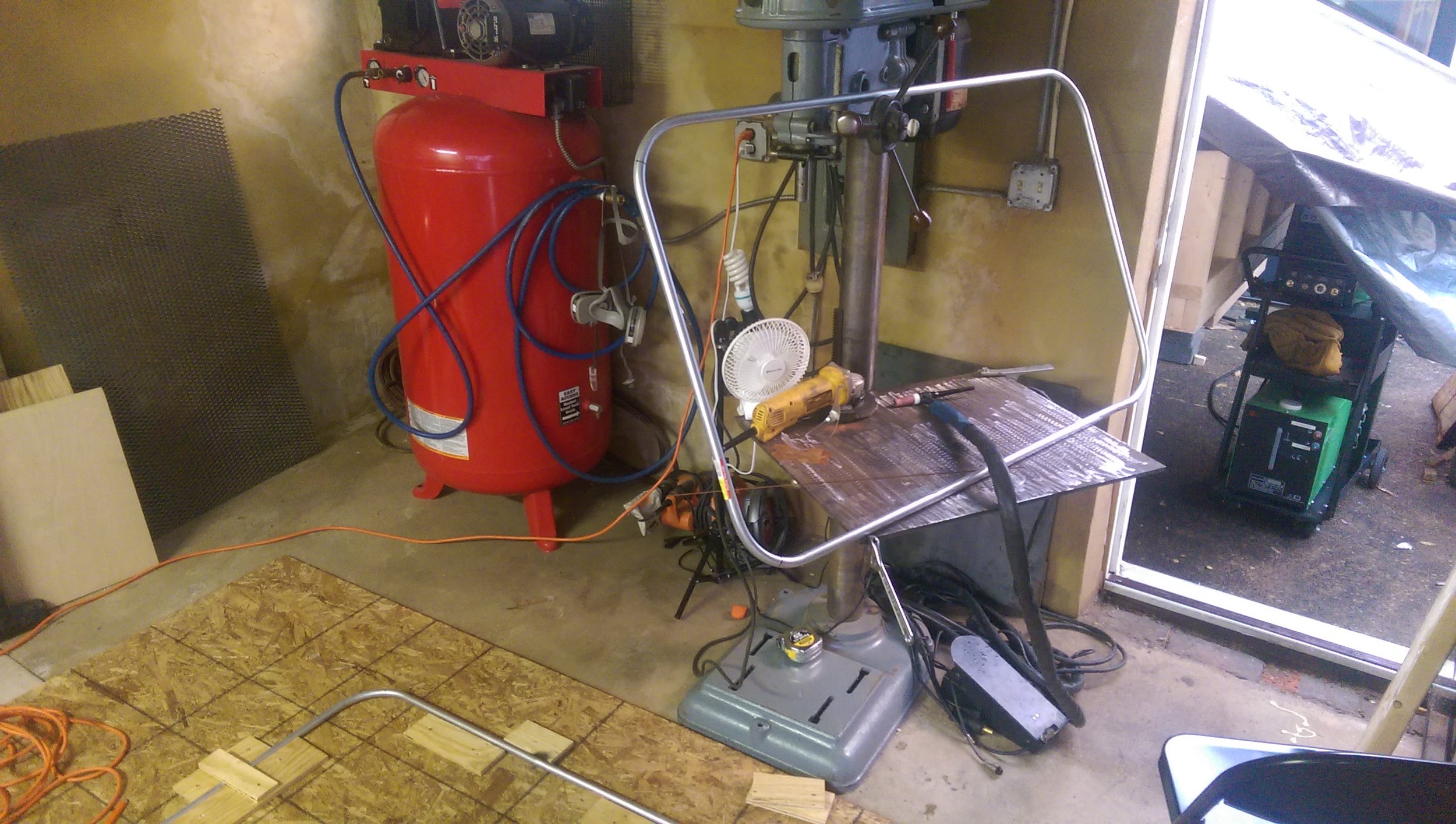
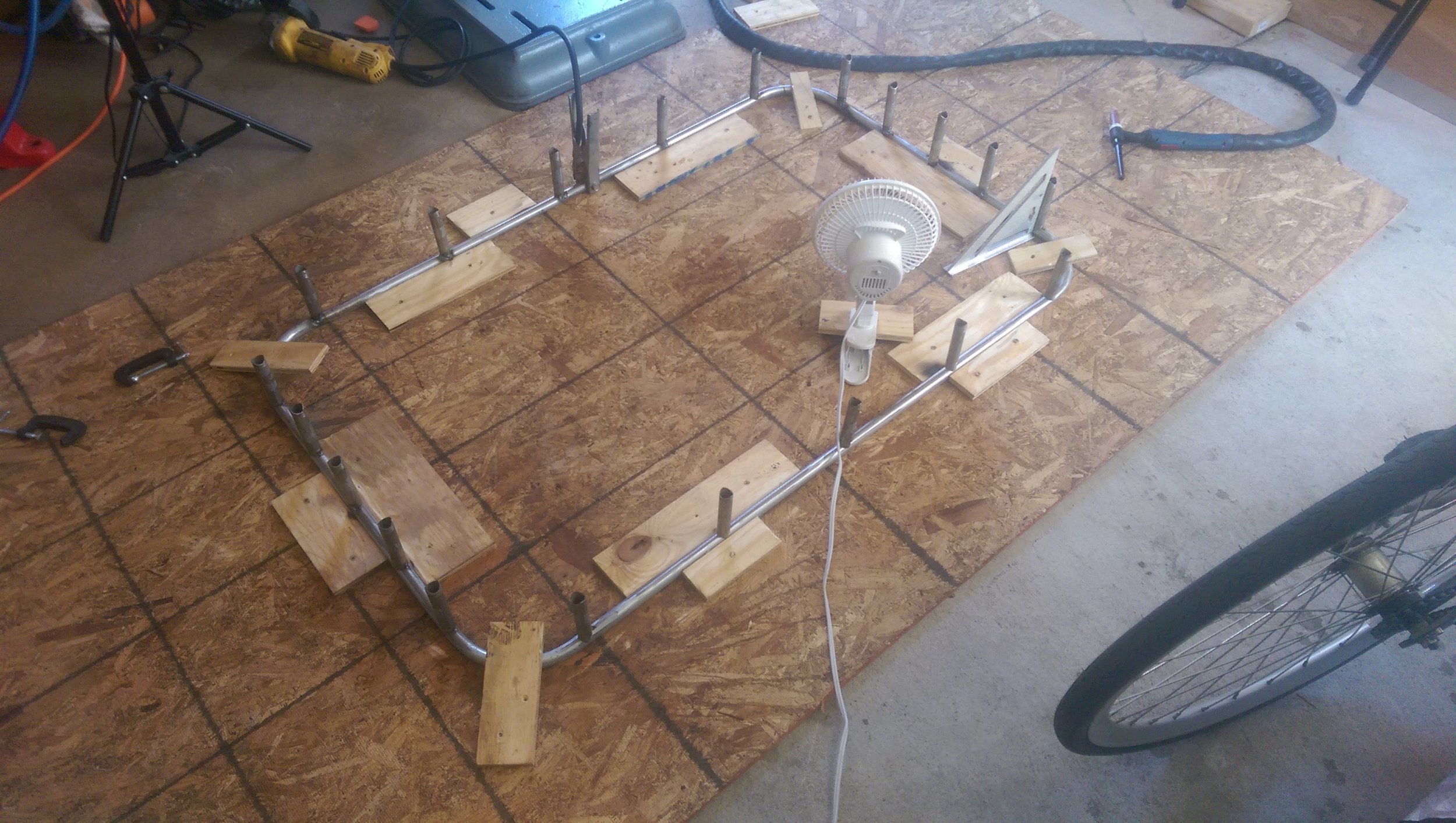
When the hoops were bent I layed out a board and screwed in blocks to form a layout jig for welding in the missing sections and ultimate assembly:

Once in the jig, I tacked the parts together and then removed to finish welding. Not pictured is my burning off some of the galvanized coating with a torch. This was pretty tedious around the joints and didn't help much.

I already was not enjoying the smoke and poor welds from the galvanized joints, so I though I'd use acid to remove the coating from the ends of the uprights. Here I just dipped the ends in Muriatic (Hydrocloric) acid for a few minutes until the coating was eaten away, then quenched in a solution of Baking Soda and water to neutralize the acid. It seemed to work pretty well:

Next I tacked in the uprights spaced evenly on the lower hoop:

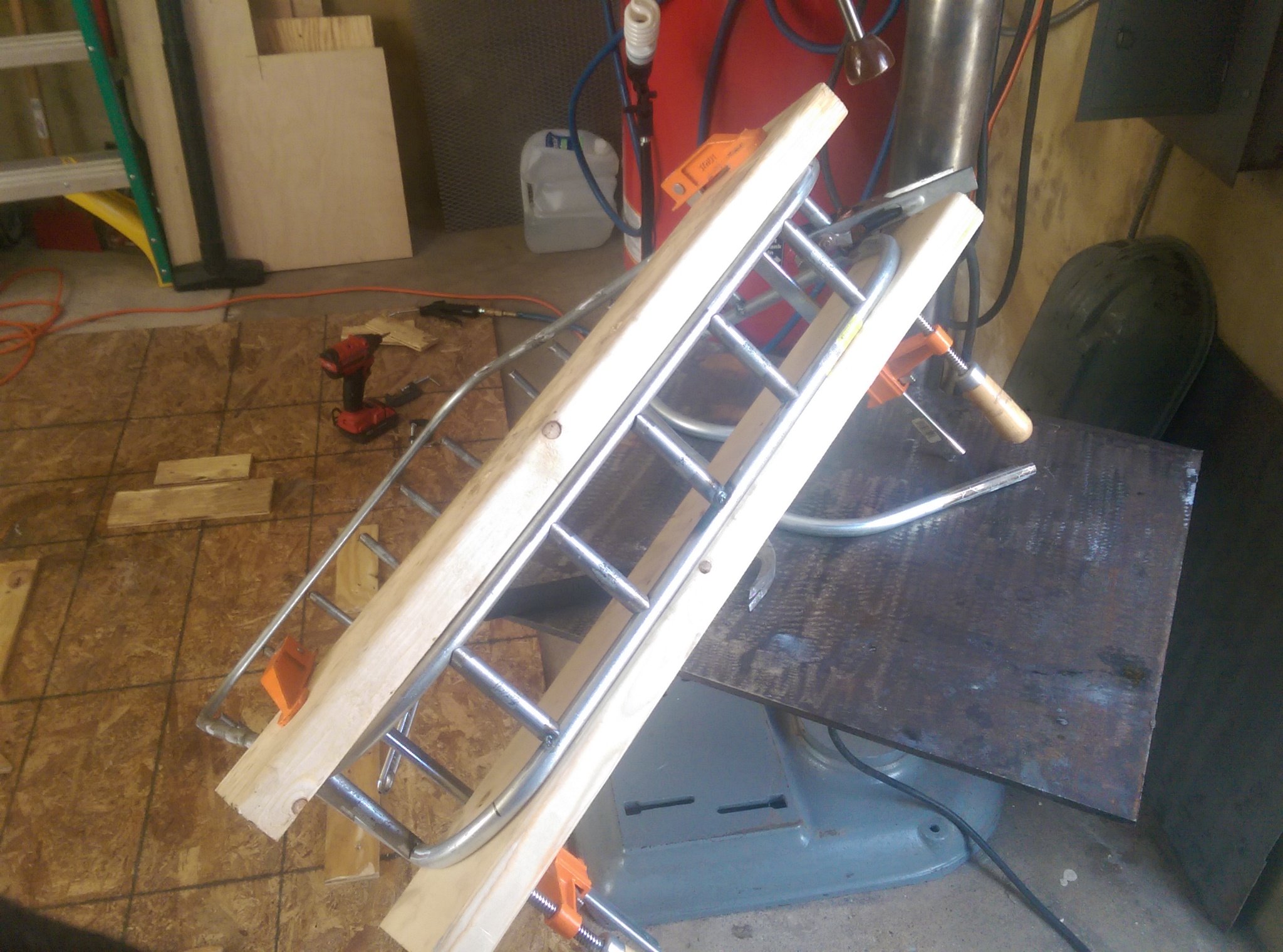
Then positioned the top hoop against the upright tubes, and used two boards to clamp it in place. This let me tap the tubes into alignment with a hammer and get once side correct. I repeated on the other side, aligning the tubes to fit:

Then began the tedious process of welding the edges of the notched tubes all the way around the frame:

After the frame was welded, I cut, notched and etched the longer tubes. (I ran out of stock so only did four.)

I welded them into place after I had a chance to cut the lower expanded metal base plate to shape. I made small clearance cuts so that the metal would fit around all the tubes. It was easier than it sounds, but I wish I had put a witness mark, cause finding the original orientation again later was a pain:
Once the bulk of the frame was welded together, I cut simple bar stock to the right lengths to form both the light bar mounts and the roof mount plates. Here they are being made up:
Here are the light mounts:
And the roof mount plates. These are angled slightly inward to match up with the angle of the curved roof at that point. They are welded on the edge and along where the mate the cross tube:
When the frame was all welded together (this took a while, and there were rain storms; I needed to take time to avoid the fumes, and the tubing was thin) I temporarily attached the vibration mounts so that I could mark and drill the holes in the roof. The mounts work quite well and it looks great on the roof.
The process was pretty simple to make the base rack, but it was a pretty tedious and time consuming job. Next time I'm going to spend the extra money on higher quality, and un-coated tube. See the completion of the rack build down in the "finishing" section.
Light Bar
Parallel to the construction of the rack itself, when it was pouring rain, or I was exhausted, I changed focus to preparing the light bar for installation. My plan was to paint the housing to match the frame, and use a mil-spec connector to cleanly pass power from the cab to the roof.
I disassembled the light bar, to both prepare for paint and investigate how I could change the cord:
This cable could be easily replaced with the one that is already attached to the female end of the connector. I wanted to make a simple switch box with fuse for the cab, that could be mounted under the connector. I stared by modeling it up:
Then printed the box out on the 3D printer along with a thing top that could be screwed on. It's great being able to design and test the box in CAD and then boom; it exists!
This box is designed to mount using the same mounting screws as the mil-spec connector. This way the wire entrance is hidden behind the box, and I don't have to add extra screw holes to the roof. I had a random switch and fuse holder in my parts boxes around which I designed the box. It all went together quite nicely:
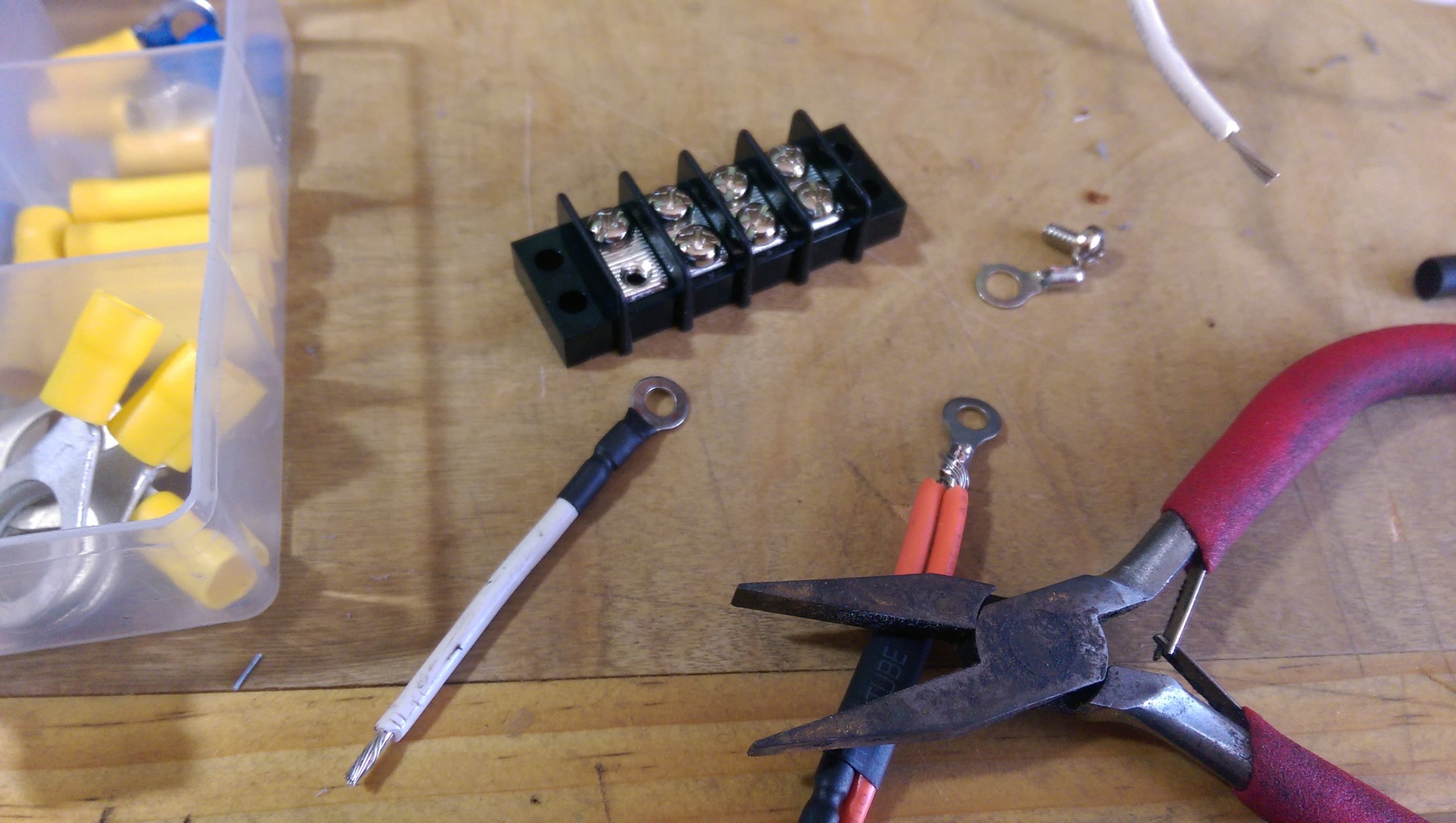
To prepare the truck for the installation I added a simple terminal block to the engine bay wired directly to the battery, this should help with any future power needs (like the Arduino controlled car dashboard):
I cut and pulled out the stock wire on the light bar, and then pushed the similarly sized pre-wired mill spec tail. Soldering was a little tricky inside, but it all fit together:
Drilling the holes for the connector was a little hairy, and I wasn't too pleased with the finish, but I think a little silicone will improve the seal in addition to the mil-spec connector gasket. Here the connector passes through the hole and is temporarily held in place with nuts:
Then I just bolted the switch box in place, tightened down the bolts and used zip-tie mounts to thread the 14 gauge appliance cable over the visor and down the A pillar to a hole and finally into the engine bay for connection to the terminal block.
Here is the finished switch box, pretty clean if I say so:
Lessons learned from the light bar install would mainly be that I should have just used the existing wiring and either extended or adapted it with my connector. The tail I had had slightly lower gauge wires, and the glue heat shrink encased the whole connector. I didn't want to spend too much on this, so I just went with what I had, versus buying a new connector or more heat shrink.
Another thing I notice about this particular light bar, is that some of the light reflects down on the hood, lighting it up. I'd prefer to have it all cast forward, so may be adding a mirrored reflector panel to bounce that light forward. Something like this:
But for now I'm happy with this as it is.
Finishing
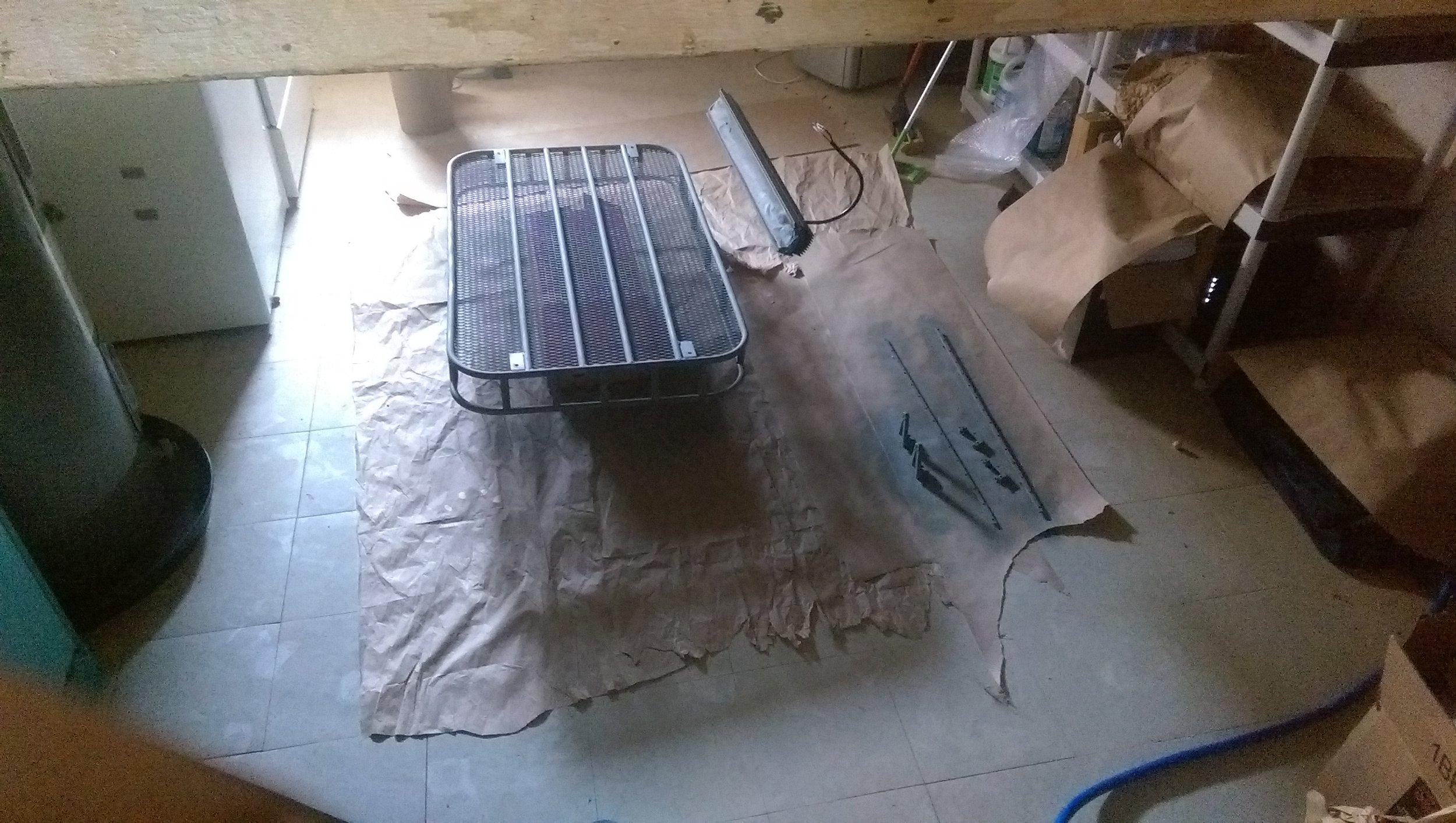
To finish this project I thought a flat, rust color would compliment the existing rust on the truck and subtly be the red to go along with the blue and white on the truck. I masked off the LED circuit board, cleaned everything with acetone and then sprayed on an etching primer:
Then sprayed it all with Rusty Metal Primer:
I also painted all the light bar parts to match and assembled that together:
The rack was mounted on the four vibration mounts, with 3/4" clearance holes through the double sheet metal of the roof:
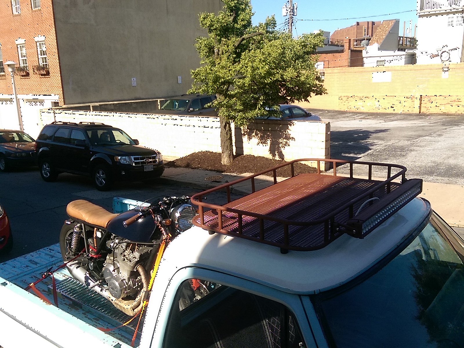
Here is the rack mounted:
And finally the finished product with the light bar mounted. I hope you enjoyed this build log, and perhaps it will inspire you to do the same!
Fully Gallery