Introduction
Of the many skills I learned while apprenticing in Japan, one was that speed and efficiency was as important as the quality of the work. They were inextricably linked. Though less common in the modern age of metal, plastic, and throw away goods, mortise and tenon joinery is, as all woodworkers know, a timeless method of building frames for strength and longevity. They are, however, somewhat time consuming to produce, considering one needs a square/rectangular mortise and a precisely fitting tenon, with clean shoulders to make for a good and aesthetically pleasing joint. There are many methods of using machine tools to improve the speed of this process, however none seem faster than using a tenon cutting machine like those still available in Japan.
Source Material
The inspiration for this build came from machine pictured here, a Tokiwa Kogyo combination table saw tenon cutter. Notice the main shaft connecting the table saw blade on the left with the tenon cutting blade on the right. This machine has a large adjustable table with a movable fence and depth adjustment rod. Cutting a tenon cheek requires the user to set the horizontal table height to half the thickness of the material, and set the vertical fence offset from the side of the material such that by inserting the work towards the blade, the waste is cut off down to the shoulder. The shoulders would have previously been cut around the work at this point on a sliding table saw, or my next best solution, a large sliding table saw sled.
With this project I hoped to replicate the tenon cutting functionality of this tool as a stand alone machine, and the idea to “just build one” arose in step with my noticing of a beat up old cross slide vise that would serve as a perfect control mechanism for the table. Perhaps the idea that I wouldn’t be building it completely from scratch was all the motivation I needed to derail the production of a crib and changing table to build a tool that would hopefully make those projects move faster.
The Advantage
Why might building an entire tool be preferable to using some of the other available methods to cut tenons? Namely, a table saw jig, there are those commercially made, and they can be rather quickly made, such as the one I built for my first shoji door set. Other than my default answer of “because I want to build a tool to see if I can.” There are a few distinct advantages that come with a tenon cutter such as this.
The table saw is awkward. One has to clamp the material vertically and engineer a sled to slide along the table saw fence. The force of the blade is impacting the edge of the workpiece, rather than the end, making for some unsettling torques. The work is also vertical in the air, and so the height is limited by the ceiling height. There is some danger in pushing a jig over the blade as it will always come out the other side and injure the user if they are not carful. Finally, a set up ties up the table saw, which might be otherwise used for some other task.
Undercut makes for clean joints. By feeding the end of the workpiece both into the blade and centered on it, the curvature of the cutting action is used to advantage. When properly adjusted the blade will cut deeper into the center of the material than at the edges. This results in a very small, curved recess in the shoulder of the tenon. Not only does this ensure there is no material in the tenon corner that will not allow it to fully seat in the mortise, but on smaller parts, the remaining wood between this recess and the part face can compress. A little compression can ensure a very tight fitting joint with no gaps.
Speed. There is no denying that this machine makes this task very fast. The lead screws and tolerances make for repeatable set ups, even after changing them. Additionally some forethought in the work design for symmetry of tenons can allow for whipping through the parts: insert, flip to other side, flip end for end, etc.
Notice the circular arc on top of the rectangular workpiece. Only pushing in from the end allows for this. A table saw jig would make a straight line.
Notice the “under cut” at the corner of the tenon cheek and shoulder. Also note this does not extend to the faces of the work piece. A clean corner and ensuring that the edges of the cheek seat will make for a clean joint.
Design Process
The real meat-and-potatoes of this whole contraption is the ability to precisely position the work piece both offset horizontally from the blade, and centered vertically. The center line of the work must be collinear with the radius of the blade. The cross slide vise I had was an older version of the below, commonly available from the likes of Harbor Freight. Adapting this to function as a vertical/horizontal control would save much time in construction. Essentially the machine was designed around this.

Inexpensive cross slide vise served as the inspiration and core component of the adjustment mechanism for the tenon cutter.
In fact, as the first part of the build series video explains, the design process was a matter of positioning the purchased or known elements in space and filling in the gaps with custom parts and a frame:
The blade started alone in space!
Designing a work table and fence relative to the blade determined the position of the cross slide.
The motor packaging and position determined the location of the shaft and pullies relative to the blade.
The frame was designed to connect all the parts in space. Adjustments were made to the parts to make fabrication easier, for example, moving things slightly so that holes would line up on the frame.
Below are the main parts that needed to be fabricated for the build. Additionally there were several modifications made to the cross slide mechanism. The lead screws needed adjustment to support the new handles, slots needed milling for the measuring tapes, and various holes for mounting other parts needed tapping.


The finished parts. The table and fence were machined from precision ground bar stock so that there was a very flat and smooth work surface to push the material against. The features of the shaft were machined from 1 inch ground shaft stock.
With the parts designed and positioned I could design the frame to connect them all together. Below are renderings of the completed assembly, prior to fabrication. For a more detailed walk through of the design process check out the first part of the build series video, also linked below.
Fabrication
The two stages of fabrication were the machining of the custom parts, and then the machining and welding of the frame components. I chose to machine the frame tubes to length so that there would be a very precise fit up in the welding process. I preferred to drill all the mounting holes as indicated by the CAD model, rather than position the components after-the-fact on a completed frame. By doing this I was hoping that I could control where any error might be in the alignment of components. Any minor adjustments could be made with shims or slight play in the mounting holes. Ultimately, very little shimming was required and the alignment was very good.
After all the parts were fabricated, cleaned and masked, they received a few coats of etching primer and a hammered grey paint finish. It’s amazing what a clean coat of paint can do to take a bunch of parts and unify them into a real tool. Following the main assembly I fabricated a metal blade guard and dust collector below the blade. Final assembly included mounting of a power switch and wiring up the 2HP Baldor motor.
Modifications to the cross slide parts. These cast iron pieces required a few adjustments. In this picture I make a little flat to hold the stick on scale.
Machining the drive shaft. Single point threading a fine thread on one end for the blade retaining nut.
The frame parts were rough cut on a band saw then squared up to precise length on the mill so that frame fit up was accurate.
Welding of the frame. Parts were squared up and clamped in place, tack welded in sub assemblies and then I jumped around welding all the joints to limit deformation due to heat.
Some of the parts were pre-assembled and then masked, and everything, including the frame was primed and painted with a hammered grey finish.
Lastly the scale was mounted to the cross slide and the gauge line was calibrated per some test pieces.
Results
It was a little nerve wracking to turn it on for the first time, but I was very immediately pleased with the results. Everything spun up with very little vibration and very little adjustment and calibration was required to square the fence and table to the blade. After calibrating the scales, it was effortless to cut repeatable tenon cheeks. Using it on the projects for which it was built, nearly 500 cheek cuts were completed in less than half a day. The repeatability is excellent, and I can depend that my tenon size is fixed across all parts.

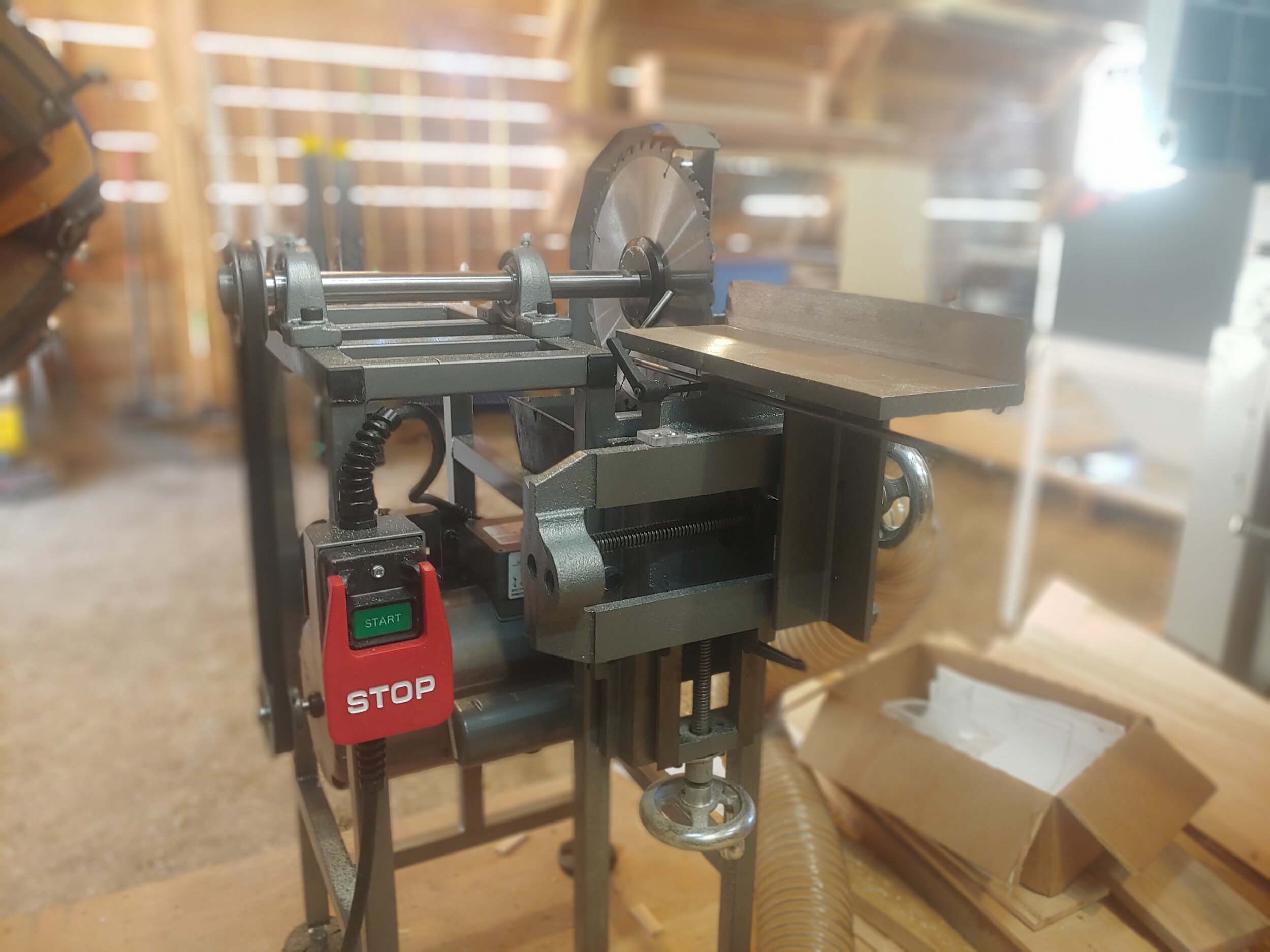
Feeding in stock to cut the tenon cheek to the shoulder cut. Difficult to see is a small L shaped rod that serves as a depth stop.
A the moment I am using the combination blade that originally came with my table saw and it works well, however at some point I’d like to upgrade to a dedicated ripping saw blade with square teeth. The nature of these cuts means the blade teeth are cutting nearly perpendicular to the wood fibers. A proper ripping blade would clear chips better and I suspect cut slightly better. There certainly is sufficient horsepower and I found no slow down whatsoever. I could push Silver Maple in as fast as I could and the 3600 RPM dealt with it effortlessly.